This is a miniature brushed DC metal gearmotor with a gearbox cross section of 10×12 mm and a 9 mm long, 3 mm diameter D-shaped gearbox output shaft.
Special Order
Shipping from $2.90
+195 more from our supplier in 7-10 days
Our Code: SKU-003505
Supplier Link: [Pololu MPN:3077]
This is a miniature brushed DC metal gearmotor with a gearbox cross section of 10×12 mm and a 9 mm long, 3 mm diameter D-shaped gearbox output shaft.
| motor/brush type | gearbox | encoder | |
|---|---|---|---|
| HPCB 6V: high-power 6V with carbon brushes | 210.59:1 with brass plates | encoder-compatible (extended motor shaft) | |
| voltage | no-load performance | stall extrapolation* |
|---|---|---|
| 6 V | 160 RPM, 150 mA | 2.8 kg⋅cm (38 oz⋅in), 1.5 A |
| * Note: Stall torque and stall current specifications are theoretical values; stalls could damage the motor or gearbox. | ||
Our Micro Metal Gearmotor family consists of tiny brushed DC metal gearmotors with nitride-hardened martensitic stainless steel gears in a wide range of gear ratios, motor windings, brushes, and encoder configurations:
| Gear ratio options | Motor winding/brush options | Encoder options |
|---|---|---|
|
|
|
The following comparison table shows basic specifications for all of the available versions (see the Micro Metal Gearmotor datasheet (5MB pdf) for additional information, including detailed performance graphs):
| Rated Voltage |
Stall Current |
No-Load Current |
No-Load Speed (RPM) |
Extrapolated Stall Torque |
Max Power (W) |
Approx Gear Ratio |
 No Encoder |
 w/ Extended Motor Shaft |
 w/ Encoder, Back Conn. |
 w/ Encoder, Side Conn. |
|
|---|---|---|---|---|---|---|---|---|---|---|---|
| (kg⋅cm) | (oz⋅in) | ||||||||||
| HPCB 12V (high-power, carbon brushes) |
|||||||||||
| 12 V | 0.75 A | 100 mA | 6800 | 0.09 | 1.3 | – | 5:1 | #3036 | #3047 | #5204 | #5205 |
| 80 mA | 3400 | 0.17 | 2.4 | 1.5 | 10:1 | #3037 | #3048 | #5206 | #5207 | ||
| 2200 | 0.25 | 3.5 | 1.4 | 15:1 | #4788 | #4789 | #5208 | #5209 | |||
| 1100 | 0.39 | 5.4 | 1.1 | 30:1 | #3038 | #3049 | #5210 | #5211 | |||
| 650 | 0.67 | 9.3 | 1.1 | 50:1 | #3039 | #3050 | #5212 | #5213 | |||
| 450 | 1.0 | 14 | 1.1 | 75:1 | #3040 | #3051 | #5214 | #5215 | |||
| 330 | 1.3 | 18 | 1.1 | 100:1 | #3041 | #3052 | #5216 | #5217 | |||
| 220 | 1.8 | 25 | 1.0 | 150:1 | #3042 | #3053 | #5218 | #5219 | |||
| 160 | 2.5 | 35 | 1.0 | 210:1 | #3043 | #3054 | #5220 | #5221 | |||
| 130 | 3.0 | 42 | 1.1 | 250:1 | #3044 | #3055 | #5222 | #5223 | |||
| 110 | 3.3 | 46 | 1.0 | 298:1 | #3045 | #3056 | #5224 | #5225 | |||
| 85 | 5.0 | 69 | 1.1 | 380:1 | #4798 | #4799 | #5226 | #5227 | |||
| 35 | 10 | 140 | – | 1000:1 | #3046 | #3057 | #5228 | #5229 | |||
| Rated Voltage |
Stall Current |
No-Load Current |
No-Load Speed (RPM) |
Extrapolated Stall Torque |
Max Power (W) |
Approx Gear Ratio |
No Encoder | w/ Extended Motor Shaft |
w/ Encoder, Back Conn. |
w/ Encoder, Side Conn. |
|
| (kg⋅cm) | (oz⋅in) | ||||||||||
| HPCB 6V (high-power, carbon brushes) |
|||||||||||
| 6 V | 1.5 A | 170 mA | 6500 | 0.09 | 1.3 | – | 5:1 | #3060 | #3082 | #5178 | #5179 |
| 150 mA | 3300 | 0.17 | 2.4 | 1.3 | 10:1 | #3061 | #3071 | #5180 | #5181 | ||
| 2100 | 0.25 | 3.5 | 1.3 | 15:1 | #4786 | #4787 | #5182 | #5183 | |||
| 1100 | 0.45 | 6.2 | 1.2 | 30:1 | #3062 | #3072 | #5184 | #5185 | |||
| 650 | 0.74 | 10 | 1.2 | 50:1 | #3063 | #3073 | #5186 | #5187 | |||
| 430 | 1.1 | 15 | 1.3 | 75:1 | #3064 | #3074 | #5188 | #5189 | |||
| 330 | 1.6 | 22 | 1.3 | 100:1 | #3065 | #3075 | #5190 | #5191 | |||
| 220 | 2.0 | 28 | 1.1 | 150:1 | #3066 | #3076 | #5192 | #5193 | |||
| 160 | 2.8 | 39 | 1.1 | 210:1 | #3067 | #3077 | #5194 | #5195 | |||
| 130 | 3.2 | 44 | 1.1 | 250:1 | #3068 | #3078 | #5196 | #5197 | |||
| 110 | 3.4 | 47 | 1.0 | 298:1 | #3069 | #3079 | #5198 | #5199 | |||
| 85 | 5.0 | 69 | 1.1 | 380:1 | #4796 | #4797 | #5200 | #5201 | |||
| 33 | 11 | 150 | – | 1000:1 | #3070 | #3080 | #5202 | #5203 | |||
| Rated Voltage |
Stall Current |
No-Load Current |
No-Load Speed (RPM) |
Extrapolated Stall Torque |
Max Power (W) |
Approx Gear Ratio |
No Encoder | w/ Extended Motor Shaft |
w/ Encoder, Back Conn. |
w/ Encoder, Side Conn. |
|
| (kg⋅cm) | (oz⋅in) | ||||||||||
| HP 6V (high-power) |
|||||||||||
| 6 V | 1.6 A | 120 mA | 6100 | 0.11 | 1.5 | – | 5:1 | #1000 | #2210 | #5152 | #5153 |
| 100 mA | 3100 | 0.22 | 3.0 | 1.6 | 10:1 | #999 | #2211 | #5154 | #5155 | ||
| 2000 | 0.30 | 4.2 | 1.5 | 15:1 | #4784 | #4785 | #5156 | #5157 | |||
| 1000 | 0.57 | 7.9 | 1.5 | 30:1 | #1093 | #2212 | #5158 | #5159 | |||
| 590 | 0.86 | 12 | 1.3 | 50:1 | #998 | #2213 | #5160 | #5161 | |||
| 410 | 1.3 | 18 | 1.4 | 75:1 | #2361 | #2215 | #5162 | #5163 | |||
| 310 | 1.7 | 24 | 1.3 | 100:1 | #1101 | #2214 | #5164 | #5165 | |||
| 210 | 2.4 | 33 | 1.2 | 150:1 | #997 | #2386 | #5166 | #5167 | |||
| 150 | 3.0 | 42 | 1.1 | 210:1 | #996 | #2216 | #5168 | #5169 | |||
| 120 | 3.4 | 47 | 1.1 | 250:1 | #995 | #2217 | #5170 | #5171 | |||
| 100 | 4.0 | 56 | 1.1 | 298:1 | #994 | #2218 | #5172 | #5173 | |||
| 84 | 5.5 | 76 | 1.1 | 380:1 | #4794 | #4795 | #5174 | #5175 | |||
| 31 | 12 | 170 | – | 1000:1 | #1595 | #2373 | #5176 | #5177 | |||
| Rated Voltage |
Stall Current |
No-Load Current |
No-Load Speed (RPM) |
Extrapolated Stall Torque |
Max Power (W) |
Approx Gear Ratio |
No Encoder | w/ Extended Motor Shaft |
w/ Encoder, Back Conn. |
w/ Encoder, Side Conn. |
|
| (kg⋅cm) | (oz⋅in) | ||||||||||
| MP 6V (medium-power) |
|||||||||||
| 6 V | 0.67 A | 80 mA | 4400 | 0.06 | 0.8 | – | 5:1 | #2362 | #2376 | #5126 | #5127 |
| 70 mA | 2200 | 0.11 | 1.5 | – | 10:1 | #2363 | #2377 | #5128 | #5129 | ||
| 1400 | 0.20 | 2.8 | 0.70 | 15:1 | #4782 | #4783 | #5130 | #5131 | |||
| 720 | 0.33 | 4.6 | 0.57 | 30:1 | #2364 | #2378 | #5132 | #5133 | |||
| 420 | 0.54 | 7.5 | 0.55 | 50:1 | #2365 | #2379 | #5134 | #5135 | |||
| 290 | 0.78 | 11 | 0.54 | 75:1 | #2366 | #2380 | #5136 | #5137 | |||
| 220 | 0.94 | 13 | 0.50 | 100:1 | #2367 | #2381 | #5138 | #5139 | |||
| 150 | 1.3 | 18 | 0.48 | 150:1 | #2368 | #2382 | #5140 | #5141 | |||
| 100 | 1.7 | 24 | 0.46 | 210:1 | #2369 | #2383 | #5142 | #5143 | |||
| 88 | 2.2 | 31 | 0.48 | 250:1 | #2370 | #2384 | #5144 | #5145 | |||
| 73 | 2.4 | 33 | 0.44 | 298:1 | #2371 | #2385 | #5146 | #5147 | |||
| 57 | 3.6 | 50 | 0.53 | 380:1 | #4792 | #4793 | #5148 | #5149 | |||
| 22 | 6.7 | 93 | – | 1000:1 | #2372 | #3059 | #5150 | #5151 | |||
| Rated Voltage |
Stall Current |
No-Load Current |
No-Load Speed (RPM) |
Extrapolated Stall Torque |
Max Power (W) |
Approx Gear Ratio |
No Encoder | w/ Extended Motor Shaft |
w/ Encoder, Back Conn. |
w/ Encoder, Side Conn. |
|
| (kg⋅cm) | (oz⋅in) | ||||||||||
| LP 6V (low-power) |
|||||||||||
| 6 V | 0.36 A | 50 mA | 2500 | 0.05 | 0.7 | – | 5:1 | #1100 | #2200 | #5100 | #5101 |
| 40 mA | 1300 | 0.10 | 1.4 | – | 10:1 | #1099 | #2201 | #5102 | #5103 | ||
| 860 | 0.17 | 2.4 | 0.37 | 15:1 | #4780 | #4781 | #5104 | #5105 | |||
| 450 | 0.29 | 4.0 | 0.31 | 30:1 | #993 | #2202 | #5106 | #5107 | |||
| 270 | 0.44 | 6.1 | 0.29 | 50:1 | #1098 | #2203 | #5108 | #5109 | |||
| 180 | 0.64 | 8.9 | 0.29 | 75:1 | #2360 | #2209 | #5110 | #5111 | |||
| 130 | 0.74 | 10 | 0.25 | 100:1 | #992 | #2204 | #5112 | #5113 | |||
| 90 | 1.1 | 15 | 0.25 | 150:1 | #1097 | #2205 | #5114 | #5115 | |||
| 65 | 1.6 | 22 | 0.25 | 210:1 | #1096 | #2206 | #5116 | #5117 | |||
| 54 | 1.7 | 24 | 0.23 | 250:1 | #1095 | #2207 | #5118 | #5119 | |||
| 45 | 2.0 | 28 | 0.22 | 298:1 | #1094 | #2208 | #5120 | #5121 | |||
| 36 | 2.9 | 40 | 0.27 | 380:1 | #4790 | #4791 | #5122 | #5123 | |||
| 13 | 5.5 | 76 | – | 1000:1 | #1596 | #3058 | #5124 | #5125 | |||
Note: Stalling or overloading gearmotors can greatly decrease their lifetimes and even result in immediate damage. The recommended upper limit for instantaneous torque is 2.5 kg⋅cm (35 oz⋅in) for the 380:1 and 1000:1 gearboxes, and 2 kg⋅cm (25 oz⋅in) for all the other gear ratios; we strongly advise keeping applied loads well under this limit. Stalls can also result in rapid (potentially on the order of seconds) thermal damage to the motor windings and brushes, especially for the versions that use high-power (HP and HPCB) motors; a general recommendation for brushed DC motor operation is 25% or less of the stall current.
In general, these kinds of motors can run at voltages above and below their nominal voltages; lower voltages might not be practical, and higher voltages could start negatively affecting the life of the motor.
The 6V and 12V HPCB motors have long-life carbon brushes, and they offer the same performance at their respective nominal voltages, just with the 12 V motor drawing half the current of the 6 V motor. The 6V HP, MP, and LP motors have shorter-life precious metal brushes, which are generally lower-friction than carbon brushes and preferred for lower-current applications. The HPCB versions (shown on the left in the picture below) can be differentiated from versions with precious metal brushes (shown on the right) by their copper-coloured terminals. Note that the HPCB terminals are 0.5 mm wider than those on the other Micro Metal Gearmotor versions (2 mm vs. 1.5 mm), and they are about 1 mm closer together (6 mm vs. 7 mm).
Micro Metal Gearmotor HPCB with long-life carbon brushes (left) next to one with precious metal brushes.
Micro Metal Gearmotor HPCB long-life carbon brushes (left) next to Micro Metal Gearmotor HP precious metal brushes (right).
In addition to standard versions that are not intended for use with encoders, we have versions of our Micro Metal Gearmotors available with integrated 12 CPR quadrature encoders on the motor shafts (i.e. on the inputs to the gearbox). These are available in two styles—back connector and side connector—and work with our assortment of 6-pin JST SH-style cables and 6-pin JST SH-style connector boards (cables are not included). A plastic snap-on housing covers the encoder disc and electronics.
We also have motor versions available with an extended motor shaft for adding your own encoder. This 1 mm diameter shaft extends 4.5 mm from the rear of the motor and rotates at the same speed as the input to the gearbox. These versions work with our separately available encoders for Micro Metal Gearmotors.
The table below shows the exact gear ratios for our Micro Metal Gearmotors. All gearboxes have the same overall dimensions except for 1000:1, which is 3.5 mm longer than the others. The gearboxes use brass plates on all versions except 380:1, which has steel plates for increased durability and resistance to wear from radial loads.
Please note that the higher gear ratios can generate enough torque to damage themselves if exposed to loads beyond what they are rated for (25 kg⋅mm for 1000:1 and 380:1, 20 kg⋅mm for everything else). The point of these higher gear ratios is not to deliver more overall torque but rather to allow for slower speeds at a given voltage and to draw less current for a given torque within its rated operating range.
Our Micro Metal Gearmotors all have gearboxes with a 10 × 12 mm cross section and a 9 mm-long, 3 mm-diameter D-shaped gearbox output shaft. The gearbox length is the same for all gear ratios except 1000:1, which is 3.5 mm longer than the others. On versions without an encoder, the motor fits entirely within the 10 × 12 mm gearbox cross section. The two encoder options fit within the gearbox cross section on the side opposite the connector and extend past it by 3 mm or 4 mm on the connector side, depending on the connector orientation; for the other two sides, the encoder extends past the gearbox cross section by 0.25 mm.
In terms of size, these gearmotors are very similar to Sanyo’s popular 12 mm NA4S DC gearmotors, and gearmotors with this form factor are sometimes also referred to as N20 motors. The versions with carbon brushes (HPCB) have slightly different terminal and end-cap dimensions than the versions with precious metal brushes, but all of the other dimensions are identical.
See our detailed dimension diagrams (635k pdf) for more information.
Gearmotor details:
| motor/brush type | gearbox | encoder | |
|---|---|---|---|
| HPCB 6V: high-power 6V with carbon brushes | 210.59:1 with brass plates | encoder-compatible (extended motor shaft) | |
Key specifications:
| voltage | no-load performance | stall extrapolation* |
|---|---|---|
| 6 V | 160 RPM, 150 mA | 2.8 kg⋅cm (38 oz⋅in), 1.5 A |
| * Note: Stall torque and stall current specifications are theoretical values; stalls could damage the motor or gearbox. | ||
Exact gear ratio: ``(25×34×34×35×38) / (12×9×13×13×10) ~~ bb(210.59:1)``
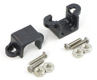  |
Black micro metal gearmotor mounting bracket pair with included screws and nuts. |
|---|
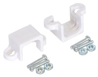  |
White micro metal gearmotor mounting bracket pair with included screws and nuts. |
|---|
  |
Side-by-side comparison of Magnetic Encoder with Top-Entry Connector (left), Side-Entry Connector (centre), and 2mm-pitch through-holes (right). |
|---|
  |
Micro Metal Gearmotor with Back-Entry, 2-Pin JST SH-Style Connector Board and cable (cable not included). |
|---|
  |
Micro Metal Gearmotor with Side-Entry, 2-Pin JST SH-Style Connector Board and cable (cable not include). |
|---|
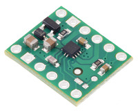  |
MP6550 Single Brushed DC Motor Driver Carrier. |
|---|
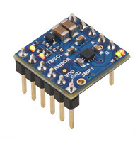  |
Motoron M1T550/M1U550 Single Motor Controller (Header Pins Soldered). |
|---|
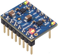  |
Motoron M2T550/M2U550 Dual Motor Controller (Header Pins Soldered). |
|---|
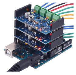  |
Three Motoron M3S550 shields being controlled by an Arduino Uno. |
|---|
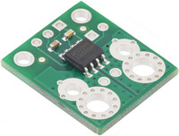  |
ACS724LLCTR-2P5AB Current Sensor Carrier -2.5A to +2.5A. |
|---|
We also incorporate these motors into some of our products, including our Zumo robot and 3pi robot :
| Size: | 10 × 12 × 25 mm1 |
|---|---|
| Weight: | 9.5 g |
| Shaft diameter: | 3 mm2 |
| Gear ratio: | 210.59:1 |
|---|---|
| No-load speed @ 6V: | 160 rpm3 |
| No-load current @ 6V: | 0.15 A4 |
| Stall current @ 6V: | 1.5 A5 |
| Stall torque @ 6V: | 2.8 kg·cm5 |
| Max output power @ 6V: | 1.1 W |
| Encoder: | encoder-compatible (extended motor shaft) |
| Long-life carbon brushes?: | Y |
| Motor type: | 1.5A stall @ 6V (HPCB 6V - carbon brush) |
| Max efficiency @ 6V: | 31 % |
|---|---|
| Speed at max efficiency: | 120 rpm |
| Torque at max efficiency: | 0.59 kg·cm |
| Current at max efficiency: | 0.40 A |
| Output power at max efficiency: | 0.74 W |
This file contains 3D models (in the step file format) of the for the various versions of the Micro Metal Gearmotors.
No! Stalls can result in rapid (potentially on the order of seconds) thermal damage to the motor windings and brushes; a general recommendation for brushed DC motor operation is 25% or less of the stall current, which means keeping continuously applied loads around 25% or less of the stall torque.
Additionally, for many of our gearmotors with high gear ratios, the extrapolated stall torque is beyond what the gearboxes are designed to handle, and a stall could instantly damage the gears. Make sure to keep applied loads within the published limits for your gearmotor.