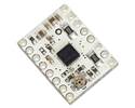
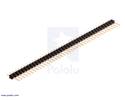
This version of our TB67S581FNG Stepper Motor Driver Carrier ships with male header pins installed , so no soldering is required to use it with an appropriate 16-pin socket or solderless breadboard. See the TB67S581FNG Stepper Motor Driver Carrier product page for more information about the driver.
Special Order
Shipping from $7.90
+129 more from our supplier in 7-10 days
Our Code: SKU-010765
Supplier Link: [Pololu MPN:2989]
This version of our TB67S581FNG Stepper Motor Driver Carrier ships with male header pins installed, so no soldering is required to use it with an appropriate 16-pin socket or solderless breadboard. See the TB67S581FNG Stepper Motor Driver Carrier product page for more information about the driver.
| Size: | 0.6″ × 0.8″ |
|---|---|
| Weight: | 2.5 g |
| Minimum operating voltage: | 8.2 V |
|---|---|
| Maximum operating voltage: | 44 V |
| Continuous current per phase: | 1.5 A1 |
| Maximum current per phase: | 2.2 A2 |
| Minimum logic voltage: | 2.5 V3 |
| Maximum logic voltage: | 5.25 V3 |
| Microstep resolutions: | full, 1/2, 1/4, 1/8, 1/16, and 1/32 |
| Reverse voltage protection?: | N |
| Header pins: | soldered |
| PCB dev codes: | md20b |
|---|---|
| Other PCB markings: | blank white box |
This DXF drawing shows the locations of all of the board’s holes.
This Arduino library, written by forum member laurb9, allows users to control a stepper motor with our A4988, DRV8825, DRV8834, and TB67S581FNG"-based carriers (for the TB67S581FNG, use the library code for the DRV8825 as the TB67S581FNG is Toshiba’s version of the DRV8825). The library has functions that enable users to set rotational rate, change microstepping mode, and specify how many steps to take or specify how many degrees to rotate.
Yes. To avoid damaging your stepper motor, you want to avoid exceeding the rated current, which is 600 mA in this instance. All of our stepper motor drivers let you limit the maximum current, so as long as you set the limit below the rated current, you will be within spec for your motor, even if the voltage exceeds the rated voltage. The voltage rating is just the voltage at which each coil draws the rated current, so the coils of your stepper motor will draw 600 mA at 3.9 V. By using a higher voltage along with active current limiting, the current is able to ramp up faster, which lets you achieve higher step rates than you could using the rated voltage.
If you do want to use a lower motor supply voltage for other reasons, consider using our DRV8834 or STSPIN-220 low-voltage stepper motor drivers.
Yes, you do! Setting the current limit on your stepper motor driver carrier before connecting your motor is essential to making sure that it runs properly. An appropriate current limit also ensures that your motor is not allowed to draw more current than it or your driver can handle, since that is likely to damage one or both of them.
Setting the current limit on our A4988, DRV8825, DRV8824, DRV8834, DRV8880, STSPINx20, and TB67SxFTG stepper motor driver carriers is done by adjusting the on-board potentiometer. We strongly recommend using a multimeter to measure the VREF voltage while setting the current limit so you can be sure you set it to an appropriate value (just turning the pot randomly until things seem to work is not a good approach). The following video has more details on setting the current limit:
Measuring the current draw at the power supply does not necessarily provide an accurate measure of the coil current. Since the input voltage to the driver can be significantly higher than the coil voltage, the measured current on the power supply can be quite a bit lower than the coil current (the driver and coil basically act like a switching step-down power supply). Also, if the supply voltage is very high compared to what the motor needs to achieve the set current, the duty cycle will be very low, which also leads to significant differences between average and RMS currents: RMS current is what is relevant for power dissipation in the chip but many power supplies won’t show that. You should base your assessment of the coil current on the set current limit or by measuring the actual coil currents.
Please note that while the TB67S581FNG driver IC is rated for up to 2.5 A per coil, the 0.5 W current sense resistors are only rated for 2.2 A, and the chip by itself will overheat at lower currents. We have found that it generally requires a heat sink to deliver more than approximately 1.5 A per coil, but this number depends on factors such as ambient temperature and air flow. For example, sealing three TB67S581FNG driver carriers in close proximity in a small box will cause them to overheat at lower currents than a unit by itself in open air.
The following is a list of official distributors who have purchased this product in the last year. You can also order directly from this website (we ship worldwide) or visit our full list of distributors.
 |
EXP GmbH
Zinzinger Str. 34 |
|---|
 |
Vanallesenmeer.nl
Noordelijke Esweg 19 |
|---|
|
The Pi Hut
Homefield Road |
|---|