This board is a simple carrier of Allegro’s ACS71240KEXBLT-010B3 Hall effect-based linear current sensor, which offers a low-resistance (~0.6 mΩ) current path and a high 120 kHz bandwidth for fast response times.
Special Order
Shipping from $7.90
+120 more from our supplier in 7-10 days
Our Code: SKU-010503
Supplier Link: [Pololu MPN:5240]
 |
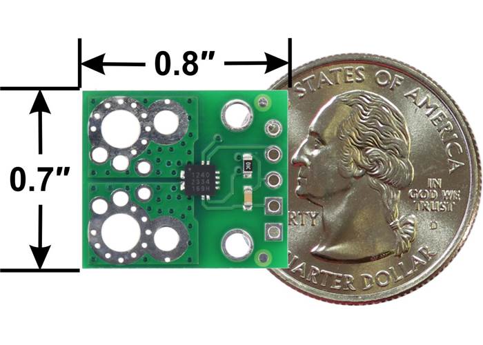
ACS71240 Current Sensor Carrier basic dimensions with US quarter for size reference.
We are offering these breakout boards with support from Allegro Microsystems as an easy way to use or evaluate their ACS71240 Hall effect-based linear current sensors; we therefore recommend careful reading of the ACS71240 datasheet before using this product. The following list details some of the sensor’s key features:
The pads are labelled on the bottom silkscreen. The silkscreen also shows the direction that is interpreted as positive current flow via the +i arrow.
ACS71240KEXBLT-010B3 Current Sensor Carrier -10A to +10A, 3.3V, bottom view. |
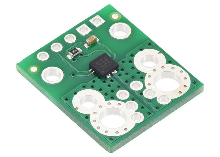
ACS71240 Current Sensor Carrier. |
This carrier features the ACS71240KEXBLT-010B3, which operates at 3.3 V and is designed for bidirectional input current from -10 A to +10 A. This version can be visually distinguished from the other versions by the “3V3 B10” printed on the bottom side, as shown in the left picture above.
| Part Suffix | Range | Sensitivity | Fault Trip Level | Supply Voltage |
|---|---|---|---|---|
| 010B3 | ±10 A (bidirectional) | 132 mV/A | ±10 A | 3.3 V |
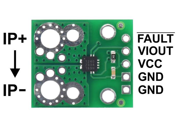
ACS71240 Current Sensor Carrier pinout.
This sensor has five required connections: the input current (IP+ and IP-), logic power (VCC and GND), and the sensor output (VIOUT).
The sensor requires a supply voltage of 3.0 V to 3.6 V to be connected across the VCC and GND pads, which are labelled on the bottom silkscreen. The sensor outputs an analogue voltage on VIOUT that is centred at 1.65 V and changes by 132 mV per amp of input current, with positive current increasing the output voltage and negative current decreasing the output voltage:
``text(VIOUT) = 1.65 V + 0.132 V/A * text(IP)``
``text(IP) = (text(VIOUT) – 1.65 V) / (0.132 V/A) = (text(VIOUT) – 1.65 V) * 7.58 A/V ``
The optional FAULT pin is normally at VCC and is pulled low when the IP current magnitude exceeds 10 A in either direction. This pin only asserts while the fault condition is present (it is not latched).
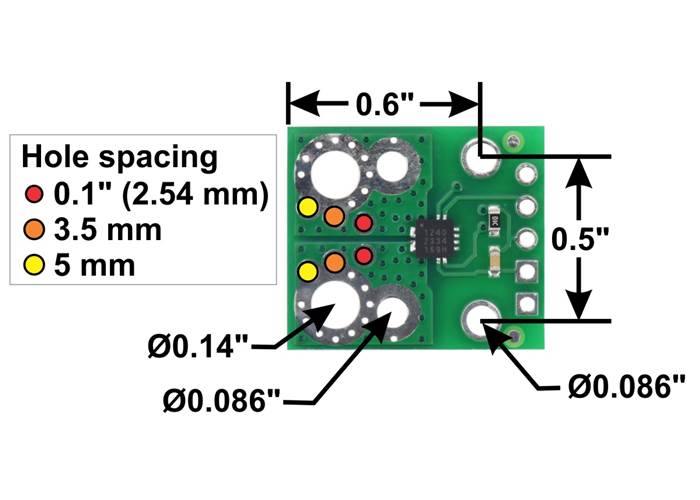
ACS71240 Current Sensor Carrier basic dimensions of current path connection holes and mounting holes.
You can insert the board into your current path in a variety of ways. Holes with 0.1″, 3.5 mm, and 5 mm spacing are available as shown in the diagram above for connecting male header pins or terminal blocks. For high-current applications, you can solder wires directly to the through-holes that best match your wires, or you can use solderless ring terminal connectors, as shown in the picture above. The largest through-holes are big enough for #6 or M3.5 screws, and the second-largest through-holes (and mounting holes) are sized for #2 or M2 screws.
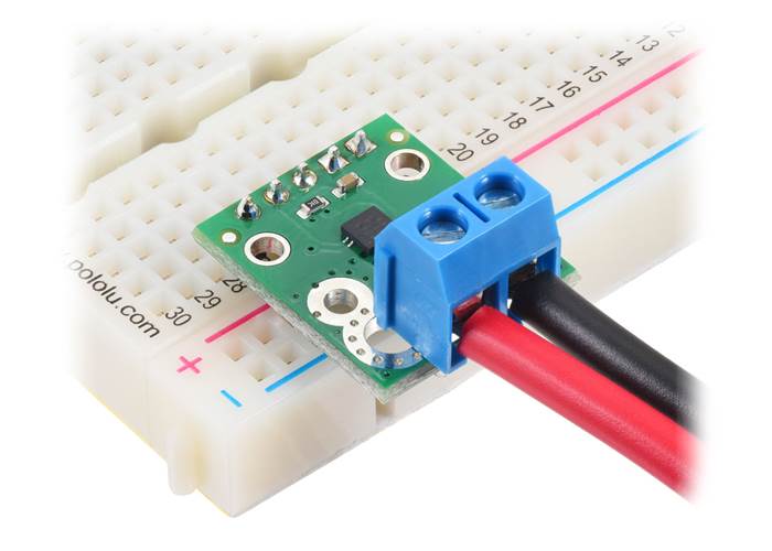
ACS71240 Current Sensor Carrier with a 5mm-pitch terminal block for the current path and header pins soldered for use with a breadboard. |
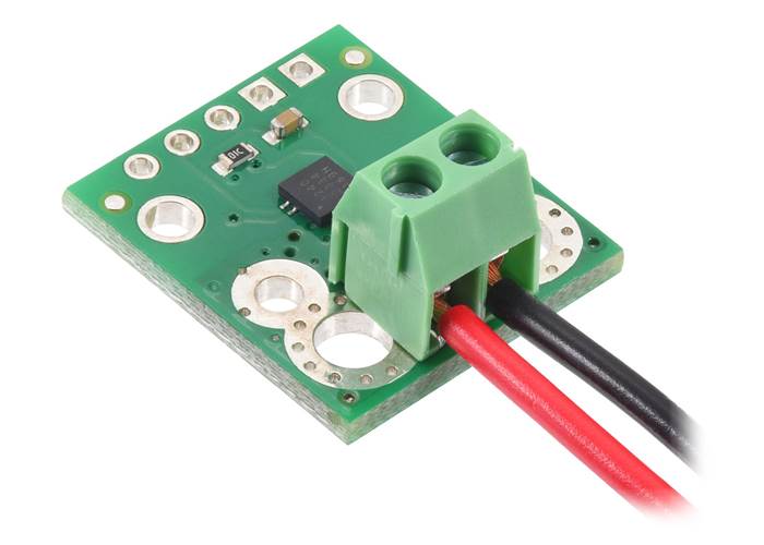
ACS71240 Current Sensor Carrier with a 3.5mm-pitch terminal block for the current path. |
ACS71240 Current Sensor Carrier with wires soldered directly to the board. |
ACS71240 Current Sensor Carrier with wires connected via solderless ring terminals. |
Warning: This product is intended for use below 30 V. Working with higher voltages can be extremely dangerous and should only be attempted by qualified individuals with appropriate equipment and protective gear.

ACS72140 current sensor carrier schematic diagram.
The dimension diagram is available as a downloadable PDF (274k pdf).
| Size: | 0.7" x 0.8" |
|---|---|
| Weight: | 1.1 g |
| Current sense: | 0.132 V/A |
|---|---|
| Minimum logic voltage: | 3.0 V |
| Maximum logic voltage: | 3.6 V |
| Supply current: | 12 mA1 |
| Version: | -10A to +10A (bidirectional 10A) |
| Current sensor: | Allegro ACS71240KEXBLT-010B3 |
| PCB dev codes: | cs02b |
|---|---|
| Other PCB markings: | 0J7387 |
| Other PCB markings: | 3V3 B10 |
This DXF drawing shows the locations of all of the board’s holes.
This is the application note referenced on page 16 of the ACS724 datasheet and page 22 of the ACS71240 datasheet. The ACS720 is used validate the test methods presented, but these same methods and principles would also apply to the ACS724 and the ACS71240.
Allegro product page for the ACS71240, where you can find additional application notes and other resources.