This is the compact version of a simple carrier for Allegro’s CT432-HSWF50DR TMR-based, electrically isolated current sensor that is optimised for high dV/dt applications and offers a high 1 MHz bandwidth with low noise. The typical primary current path resistance of the sensor IC is 1 mΩ.
Special Order
Shipping from $7.90
+189 more from our supplier in 7-10 days
Our Code: SKU-010615
Supplier Link: [Pololu MPN:5306]
 |
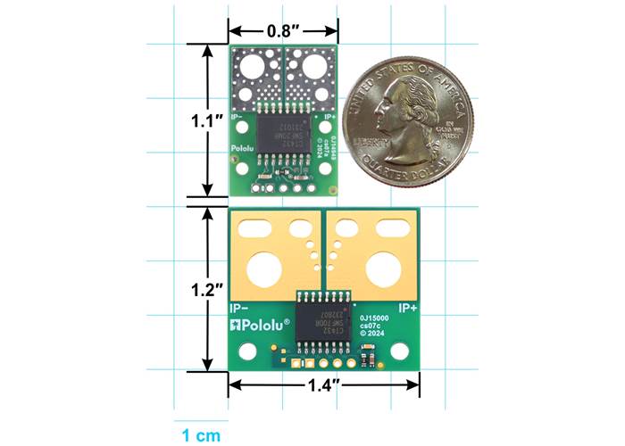
CT432/CT433 TMR Current Sensor Compact Carrier (top) and Large Carrier (bottom) size comparison.
We are offering these breakout boards with support from Allegro Microsystems as an easy way to use or evaluate their CT432/CT433 tunneling magnetoresistance (TMR), electrically isolated, high-bandwidth current sensors that are optimised for high dV/dt applications; we therefore recommend careful reading of the applicable CT432 datasheet or CT433 datasheet before using this product. The following list details some of the sensors’ key features:
The connection points are labelled on the silkscreen, which is on the bottom side of the compact versions and on both sides of the large versions. The bottom silkscreen also shows the direction that is interpreted as positive current flow via the +i arrow.
The following table lists the available CT432/CT433 carrier options:
| Pololu Item # |
Part Prefix | Supply Voltage (V) |
Part Suffix | Current Range |
Sensitivity (mV/A) |
Zero Point | Size | PCB Details |
Price | ||
|---|---|---|---|---|---|---|---|---|---|---|---|
Compact Carrier |
#5310 | CT433 | 3.0 to 3.6 (3.3 nominal) |
20MR | Bidirectional | ±20 A | 50 | 1.65 V | 0.8″×1.1″ | 2 layers, 2-oz copper |
$8.95 |
| #5311 | 30MR | ±30 A | 33.3 | ||||||||
| #5313 | 50MR | ±50 A | 20 | 4 layers, 2-oz copper |
$9.95 | ||||||
| #5300 | CT432 | 4.75 to 5.5 (5 nominal) |
20MR | ±20 A | 100 | 2.5 V | 2 layers, 2-oz copper |
$8.95 | |||
| #5301 | 30MR | ±30 A | 66.7 | ||||||||
| #5303 | 65MR | ±65 A | 30.8 | 4 layers, 2-oz copper |
$9.95 | ||||||
| #5306 | 50DR | Unidirectional | 0-50 A | 80 | 0.5 V | ||||||
| #5308 | 70DR | 0-70 A | 57.1 | ||||||||
Large Carrier |
#5333 | CT433 | 3.0 to 3.6 (3.3 nominal) |
50MR | Bidirectional | ±50 A | 20 | 1.65 V | 1.4″×1.2″ | 6 layers, 2-oz copper |
$12.95 |
| #5323 | CT432 | 4.75 to 5.5 (5 nominal) |
50MR | ±65 A | 30.8 | 2.5 V | |||||
| #5326 | 50DR | Unidirectional | 0-50 A | 80 | 0.5 V | ||||||
| #5328 | 70DR | 0-70 A | 57.1 | ||||||||
Alternatives available with variations in these parameter(s): current range Select variant…
|
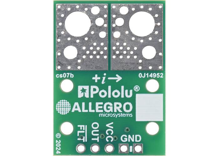
Bottom view of the CT432/CT433 TMR Current Sensor Compact Carrier, 4-layer PCB (cs07b). |
This compact carrier features the CT432-HSWF50DR, which is intended for nominal 5 V operation and is designed for unidirectional input current from 0 A to 50 A. This version can be visually distinguished from the other versions by the part number printed on the sensor IC, as shown in the left picture above (the bottom silkscreen also has a blank white box that can be used for adding customised identifying markings).
| Part Prefix | Part Suffix | Range | Supply Voltage | Sensitivity | Zero Point | Size | PCB layers |
|---|---|---|---|---|---|---|---|
| CT432 | 50DR | 0-50 A (unidirectional) | 4.75 V to 5.5 V | 80 mV/A | 0.5 V | 0.8″×1.1″ | 4 |
A larger carrier with a 6-layer PCB is also available for this sensor IC with room for larger connectors and thicker wires for the high-current path, offering different ways to use or evaluate this current sensor.
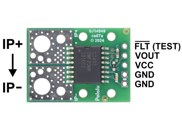
CT432/CT433 TMR Current Sensor Compact Carrier pinout.
This sensor has five required connections: the input current (IP+ and IP-), logic power (VCC and GND), and the sensor output (VOUT).
The sensor requires a supply voltage of 4.75 V to 5.5 V to be connected across the VCC and GND pads, which are labelled on the bottom silkscreen. The sensor outputs an analogue voltage on VOUT that has a zero point at 0.5 V and increases by 80 mV per amp of input current:
``V_"OUT" = 0.5 text(V) + 0.08 text(V)/text(A) * I_"P"``
``I_"P" = (V_"OUT" – 0.5 text(V)) / (0.08 text(V)/text(A)) = (V_"OUT" – 0.5 text(V)) * 12.5 text(A)/text(V)``
The output is not ratiometric, so the zero point and sensitivity are independent of the actual supply voltage.
The optional FLT pin is normally at VCC and is pulled low when the IP current magnitude exceeds 110% of the maximum sensing range. This pin only asserts while the fault condition is present (it is not latched).
Note: The datasheet warns that using the FLT (TEST) pin as a fault output rather than grounding it will reduce the sensor’s immunity to high dV/dt events. If you do not need the fault feature, you can externally connect this pin to ground. Alternatively, we have the ability to custom-assemble these boards with this pin grounded (which would also disable the fault feature). If you are interested in customisation, please contact us.
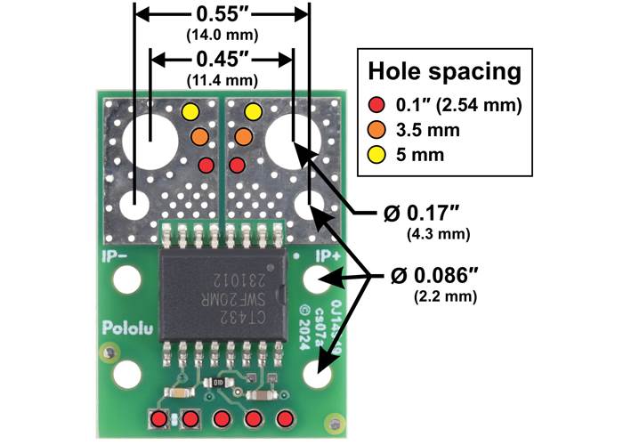
CT432/CT433 TMR Current Sensor Compact Carrier basic hole dimensions.
You can insert the board into your current path in a variety of ways. For typical high-current applications, you can solder wires directly to the through-holes that best match your wires, or you can use solderless ring terminal connectors. The largest through-holes are big enough for 10 AWG wires or #6 or M3.5 screws, and the second-largest through-holes (and mounting holes) are sized for 14 AWG wires or #2 or M2 screws. Holes with 0.1″, 3.5 mm, and 5 mm spacing are also available as shown in the diagram above for connecting male header pins or terminal blocks, but please note that these connection options are generally not suitable for high currents and could limit the usable range of the sensor.
The FLT, VOUT, VCC, and GND pins work with 0.1″-pitch header pins and are compatible with standard solderless breadboards
Warning: This product is intended for use below 30 V. Working with higher voltages can be extremely dangerous and should only be attempted by qualified individuals with appropriate equipment and experience.
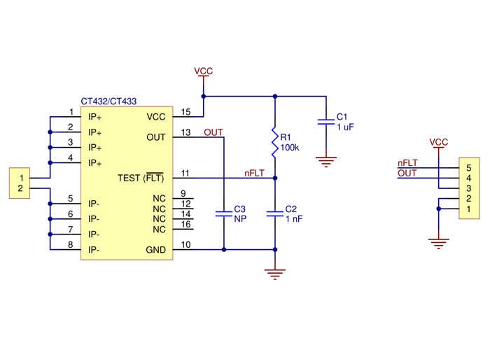
CT432/CT433 TMR Current Sensor Carrier schematic diagram.
The dimension diagram is available as a downloadable PDF (436k pdf).
 |
Thermal image of a high-current test of a Pololu current sensor carrier (not necessarily this product). |
|---|
Depending on the version, the CT432 and CT433 can measure up to ±70 A. However, the sensor chip will typically overheat at lower currents. In our tests, we found that our 2-layer CT432/CT433 compact carrier board (cs07a) could conduct about 45 A continuously, and the 4-layer compact carrier board (cs07b) could conduct about 50 A continuously, without reaching the thermal limit for the IC. (Sensors with ranges under 45 A use the cs07a board while sensors with ranges over 45 A use the cs07b board.) Our tests were conducted at approximately 25°C ambient temperature with no forced air flow.
The actual current you can pass through the sensor will depend on how well you can keep it cool. The carrier’s printed circuit board is designed to help with this by drawing heat out of the sensor chip. Solid connections to the current path pins (such as with thick soldered wires or large, tightly-secured lugs) can also help reduce heat build-up in the sensor and carrier board.
Warning: Exceeding temperature or current limits can cause permanent damage to the sensor. If you are measuring an average continuous current greater than 30 A, we strongly recommend that you monitor the sensor’s temperature and look into additional cooling if necessary.
This product can get hot enough to burn you long before the chip overheats. Take care when handling this product and other components connected to it.
We have a variety of current sensors available with different ranges, sensitivities, and features. The table below summarizes our selection of active and preferred options:
| ACS711 CurrentSensor Carriers | ACS71240 CurrentSensor Carriers | ACS724 CurrentSensor Carriers | ACS37220Current SensorCompact Carriers | ACS37220Current SensorLarge Carriers | ACS72981Current SensorCompact Carriers | ACS72981Current SensorLarge Carriers | CT432/CT433 TMRCurrent SensorCompact Carriers | CT432/CT433 TMRCurrent SensorLarge Carriers | |
|---|---|---|---|---|---|---|---|---|---|
| Sensor IC | Allegro ACS711KEXT |
Allegro ACS71240 |
Allegro ACS724LLCTR |
Allegro ACS37220 | Allegro ACS72981xLR | Allegro CT432/CT433 | |||
| Vcc range (V) | 3.0–5.5 | 3.3V versions: 3.0–3.6 5V versions: 4.5–5.5 |
4.5–5.5 | 3.3V versions: 3.15–3.45 5V versions: 4.5–5.5 |
3.3V versions: 3.0–3.6 5V versions: 4.5–5.5 |
3.3V versions (CT433): 3.0–3.6 5V versions (CT432): 4.75–5.5 |
|||
| Current range / sensitivity |
Bidirectional:(1) ±15.5 A / 90 mV/A ±31 A / 45 mV/A |
3.3V Bidirectional: ±10 A / 132 mV/A ±30 A / 44 mV/A ±50 A / 26.4 mV/A 5V Bidirectional: ±10 A / 200 mV/A ±30 A / 66 mV/A ±50 A / 40 mV/A 5V Unidirectional: 0–50 A / 80 mv/A |
5V Bidirectional:(2) ±2.5 A / 800 mV/A ±5 A / 400 mV/A ±10 A / 200 mV/A ±20 A / 100 mV/A ±30 A / 66 mV/A ±50 A / 40 mV/A 5V Unidirectional:(2) 0–5 A / 800 mv/A 0–10 A / 400 mv/A 0–20 A / 200 mv/A 0–30 A / 133 mV/A |
3.3V Bidirectional: ±100 A / 13.2 mV/A ±150 A / 8.8 mV/A 5V Bidirectional: ±100 A / 20 mV/A ±150 A / 13.3 mV/A ±200 A / 10 mV/A |
3.3V Bidirectional: ±100 A / 13.2 mV/A ±150 A / 8.8 mV/A 5V Bidirectional: ±100 A / 20 mV/A ±150 A / 13.3 mV/A ±200 A / 10 mV/A |
3.3V Bidirectional:(1) ±50 A / 26.4 mV/A ±100 A / 13.2 mV/A ±150 A / 8.8 mV/A 3.3V Unidirectional:(1) 0–50 A / 52.8 mv/A 0–100 A / 26.4 mv/A 0–150 A / 17.6 mv/A 0–200 A / 13.2 mv/A 5V Bidirectional:(2) ±50 A / 40 mV/A ±100 A / 20 mV/A ±150 A / 13.3 mV/A ±200 A / 10 mV/A 5V Unidirectional:(2) 0–100 A / 40 mv/A 0–150 A / 26.7 mv/A |
3.3V Bidirectional:(1) ±50 A / 26.4 mV/A ±100 A / 13.2 mV/A ±150 A / 8.8 mV/A 3.3V Unidirectional:(1) 0–50 A / 52.8 mv/A 0–100 A / 26.4 mv/A 0–150 A / 17.6 mv/A 0–200 A / 13.2 mv/A 5V Bidirectional:(2) ±50 A / 40 mV/A ±100 A / 20 mV/A ±150 A / 13.3 mV/A ±200 A / 10 mV/A 5V Unidirectional:(2) 0–100 A / 40 mv/A 0–150 A / 26.7 mv/A |
3.3V Bidirectional: ±20 A / 50 mV/A ±30 A / 33.3 mV/A ±50 A / 20 mV/A 5V Bidirectional: ±20 A / 100 mV/A ±30 A / 66.7 mV/A ±65 A / 30.8 mV/A 5V Unidirectional: 0–50 A / 80 mv/A 0–70 A / 57.1 mv/A |
3.3V Bidirectional: ±50 A / 20 mV/A 5V Bidirectional: ±65 A / 30.8 mV/A 5V Unidirectional: 0–50 A / 80 mv/A 0–70 A / 57.1 mv/A |
| IC path resistance | 0.6 mΩ | 0.6 mΩ | 0.6 mΩ | 0.1 mΩ | 0.2 mΩ | 1 mΩ | |||
| PCB | 2 layers, 2-oz copper |
2 layers, 2-oz copper |
2 layers, 2- or 4-oz copper(4) |
2 layers, 2-oz copper |
6 layers, 2-oz copper |
6 layers, 2-oz copper |
6 layers, 2-oz copper |
2 or 4 layers(5), 2-oz copper |
6 layers, 2-oz copper |
| Max bandwidth | 100 kHz | 120 kHz | 120 kHz(3) | 150 kHz | 250 kHz | 1 MHz | |||
| Sensing technology | Hall effect | Hall effect | Hall effect | Hall effect | Hall effect | XtremeSense™ TMR (tunneling magnetoresistance) |
|||
| Size | 0.7″ × 0.8″ | 0.7″ × 0.8″ | 0.7″ × 0.8″ | 0.7″ × 0.8″ | 1.4″ × 1.2″ | 0.7″ × 0.8″ | 1.4″ × 1.2″ | 0.8″ × 1.1″ | 1.4″ × 1.2″ |
| Overcurrent fault output | User-configurable threshold | ||||||||
| Common-mode field rejection | |||||||||
| Non-ratiometric output | |||||||||
| 1-piece price | $3.49 | $3.95 | $6.95 – $7.49 | $4.95 | $7.95 | $9.95 | $12.95 | $8.95 – $9.95 | $12.95 |
| (1) Sensitivity when Vcc = 3.3 V; sensitivity is ratiometric. | |||||||||
| (2) Sensitivity when Vcc = 5 V; sensitivity is ratiometric. | |||||||||
| (3) Bandwidth can be reduced by adding a filter capacitor. | |||||||||
| (4) ±50A version uses 4-oz copper PCB; all other versions use 2-oz copper. | |||||||||
| (5) 50A and higher versions use 4-layer PCB; all other versions use 2-layer PCB. | |||||||||
| Size: | 0.8″ × 1.1″ |
|---|---|
| Weight: | 2.3 g |
| Typical operating voltage: | 5 V |
|---|---|
| Current sense: | 80 mV/A |
| Minimum logic voltage: | 4.75 V |
| Maximum logic voltage: | 5.5 V |
| Supply current: | 6 mA1 |
| Current range: | 0A to 50A (unidirectional 50A), 5V |
| Current sensor: | Allegro CT432-HSWF50DR |
| PCB dev codes: | cs07b |
|---|---|
| Other PCB markings: | 0J14952 |
This DXF drawing shows the locations of all of the board’s holes.
Allegro product page for the CT432, where you can find additional application notes and other resources.
Allegro product page for the CT433, where you can find additional application notes and other resources.