This is a carrier board for Allegro’s A5984 microstepping bipolar stepper motor driver. It offers eight different microstep resolutions (down to 1/32-step) and has over-current and over-temperature protection, and it features an adaptive decay algorithm that automatically optimizes the motor cur...
Special Order
Shipping from $7.90
+105 more from our supplier in 7-10 days
Our Code: SKU-010644
Supplier Link: [Pololu MPN:5344]
 |

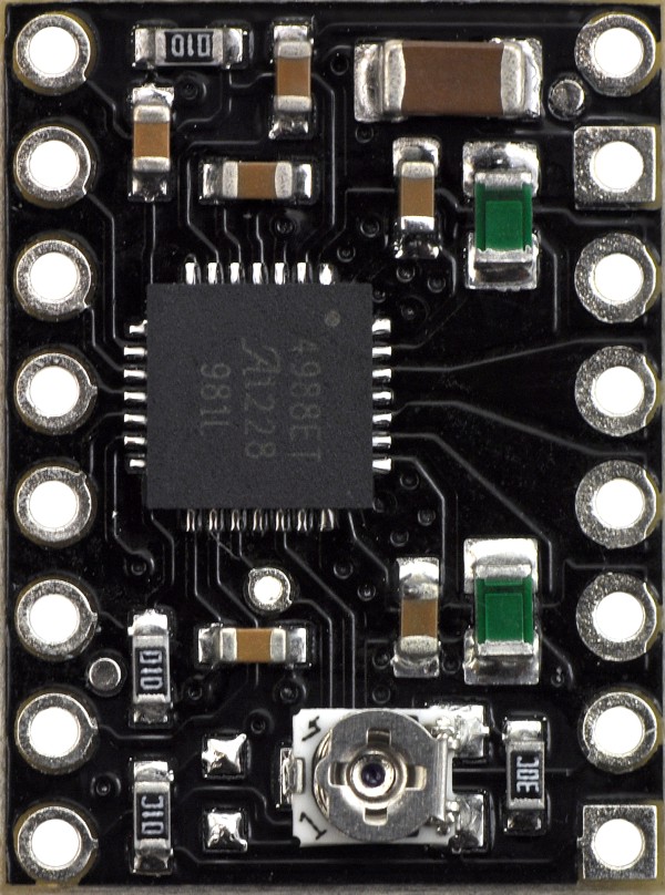
A5984 Stepper Motor Driver Carriers, bottom view with dimensions.
We are offering these carrier boards with support from Allegro Microsystems as an easy way to control bipolar stepper motors using their A5984 DMOS Microstepping Driver with Translator and Overcurrent Protection; we therefore recommend careful reading of the A5984 datasheet before using this product.
There are several different versions of A5984 carriers, and the following comparison table shows their key differences:
 Adjustable Current, Blue Edition |
 Adjustable Current |
 Fixed 1.5A@5V / 1A@3.3V, Blue Edition |
 Fixed 1A@5V / 660mA@3.3V, Blue Edition |
 Fixed 750mA@5V / 500mA@3.3V |
 Fixed 500A@5V / 330mA@3.3V |
|
|---|---|---|---|---|---|---|
| Current limit (VDD = 5 V): |
adjustable (potentiometer) 1.2 A max continuous 2 A peak* |
adjustable (potentiometer) 1 A max continuous 2 A peak* |
1.5 A* | 1 A | 750 mA | 500 mA |
| Current limit (VDD = 3.3 V): |
1 A | 660 mA | 500 mA | 330 mA | ||
| Available versions: | ||||||
| PCB layers: | 4 | 2 | 4 | 4 | 2 | 2 |
| Price without header pins: | $3.97 | $3.75 | $3.75 | $3.75 | $3.49 | $3.49 |
| Price w/headers soldered: | $4.97 | $4.75 | $4.75 | $4.75 | $4.49 | $4.49 |
| * This current exceeds what the module can deliver continuously and is only achievable for short durations or with sufficient additional cooling. | ||||||
This product ships with all surface-mount components—including the A5984 driver IC—installed as shown in the product picture.
We also have a variety of other stepper motor driver options in this same form factor with different operating profiles and features.
Some unipolar stepper motors (e.g. those with six or eight leads) can be controlled by this driver as bipolar stepper motors. For more information, please see the frequently asked questions. Unipolar motors with five leads cannot be used with this driver.
A5984 Stepper Motor Driver Carrier, Fixed 1.5A@5V / 1A@3.3V, Blue Edition. |
A5984 Stepper Motor Driver Carrier, Fixed 1.5A@5V / 1A@3.3V, Blue Edition, top view. |
A5984 Stepper Motor Driver Carrier, Blue Edition, bottom view. |
This product is the A5984 carrier with a fixed current limit of 1.5 A (VDD = 5 V) or 1 A (VDD = 3.3 V) (see below for more details). It can typically deliver phase currents up 1.2 A without a heat sink or forced air flow, and it is generally intended for 3.3 V applications, which results in a fixed current limit of 1 A. This version does not have header pins soldered or included; 0.1″ headers are available separately, as is a version of this driver with header pins already soldered.
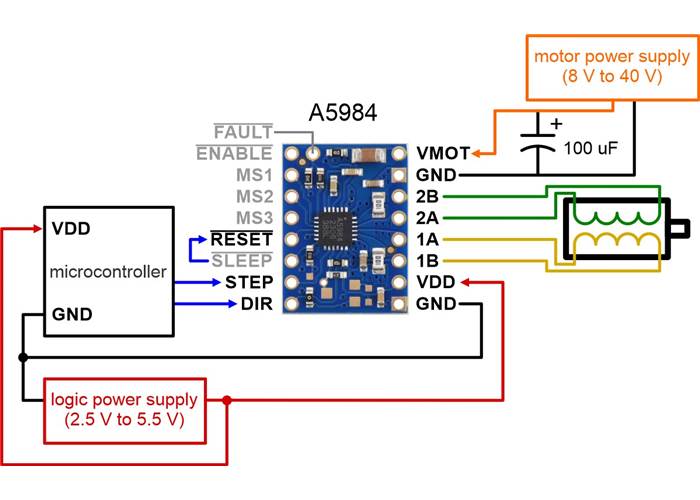
Minimal wiring diagram for connecting a microcontroller to an A5984 Stepper Motor Driver Carrier, Fixed 1.5A@5V / 1A@3.3V, Blue Edition.
The driver requires a motor supply voltage of 8 V to 40 V (absolute max) to be connected across VMOT and GND. This supply should be capable of delivering the expected stepper motor current.
Four, six, and eight-wire stepper motors can be driven by the A5984 if they are properly connected; a FAQ answer explains the proper wirings in detail.
Warning: Connecting or disconnecting a stepper motor while the driver is powered can destroy the driver. (More generally, rewiring anything while it is powered is asking for trouble.)
Stepper motors typically have a step size specification (e.g. 1.8° or 200 steps per revolution), which applies to full steps. A microstepping driver such as the A5984 allows higher resolutions by allowing intermediate step locations, which are achieved by energizing the coils with intermediate current levels. For instance, driving a motor in quarter-step mode will give the 200-step-per-revolution motor 800 microsteps per revolution by using four different current levels.
The resolution (step size) selector inputs (MS1, MS2, and MS3) enable selection from the eight step resolutions according to the table below. The driver defaults to full step with 100% current. For the microstep modes to function correctly, the current limit must be set low enough (see below) so that current limiting gets engaged. Otherwise, the intermediate current levels will not be correctly maintained, and the motor will skip microsteps.
| MS1 | MS2 | MS3 | Microstep Resolution |
|---|---|---|---|
| Low | Low | Low | Full step with 100% current |
| Low | Low | High | Half step with 100% current (also called non-circular half step) |
| Low | High | Low | 1/16 step |
| Low | High | High | 1/32 step |
| High | Low | Low | Modified full step (71% current) |
| High | Low | High | Modified half step (circular) |
| High | High | Low | 1/4 step |
| High | High | High | 1/8 step |
The rising edge of each pulse to the STEP input corresponds to one microstep of the stepper motor in the direction selected by the DIR pin. Note that the STEP and DIR pins are not pulled to any particular voltage internally, so you should not leave either of these pins floating in your application. If you just want rotation in a single direction, you can tie DIR directly to VDD or GND.
The chip has thee different inputs for controlling its power states: RESET, SLEEP, and ENABLE. The RESET pin (RST) is floating by default; this pin must be high to enable the driver (it can be connected to the adjacent SLEEP pin or directly to a logic “high” voltage between 2 V and 5.5 V, or it can be dynamically controlled from a digital output of an MCU). The default state of the SLEEP (SLP) and ENABLE (EN) pins is to enable the driver (the carrier board pulls SLEEP up to VDD and pulls ENABLE down to GND). See the datasheet for more details.
The A5984 also features an open-drain FAULT (nFAULT) output that drives low whenever the driver detects an over-current fault. The carrier board pulls this pin up to VDD, so no external pull-up is necessary on the FAULT pin. Bringing RESET or SLEEP low clears a latched fault.
To achieve high step rates, the motor supply is typically higher than would be permissible without active current limiting. For instance, a typical stepper motor might have a maximum current rating of 1 A with a 5 Ω coil resistance, which would indicate a maximum motor supply of 5 V. Using such a motor with 9 V would allow higher step rates, but the current must actively be limited to under 1 A to prevent damage to the motor.
The A5984 supports such active current limiting, and this version of the carrier has a fixed current limit set with on-board resistors. The current limit is proportional to the logic voltage, VDD; for this board, it is about 1.5 A when VDD is 5 V or 1 A when VDD is 3.3 V. More generally, the current limit in amps relates to VDD in volts as follows:
``text(Current Limit) = text(VDD) / 3.33``
You will typically want to choose a current limit that is at or below the current rating of your stepper motor.
Note: The coil current can be very different from the power supply current, so you should not expect the current measured at the power supply to match the current limit. The appropriate place to put your current meter is in series with one of your stepper motor coils. If the driver is in full-step 100% current or full-step 71% current modes, both coils will always be on and limited to 100% or 71% of the current limit setting, respectively. If your driver is in one of the microstepping modes, the current through the coils will change with each step, ranging from 0% to 100% of the set limit. See the A5984 datasheet for more information.
 |
The A5984 carrier has a maximum current rating of 2 A per coil, but the actual current you can deliver depends on how well you can keep the IC cool. The carrier’s printed circuit board is designed to draw heat out of the IC, but to supply more than approximately 1.2 A per coil, a heat sink or other cooling method is required. Operating this version with a fixed current limit of 1 A (i.e. with VDD = 3.3V) will generally not require any special cooling, but additional cooling might still be required for applications that limit heat dissipation, such as use in enclosed spaces or high ambient temperature conditions.
This product can get hot enough to burn you long before the chip overheats. Take care when handling this product and other components connected to it.
Please note that measuring the current draw at the power supply will generally not provide an accurate measure of the coil current. Since the input voltage to the driver can be significantly higher than the coil voltage, the measured current on the power supply can be quite a bit lower than the coil current (the driver and coil basically act like a switching step-down power supply). Also, if the supply voltage is very high compared to what the motor needs to achieve the set current, the duty cycle will be very low, which also leads to significant differences between average and RMS currents. Additionally, please note that the coil current is a function of the set current limit, but it does not necessarily equal the current limit setting as the actual current through each coil changes with each microstep.

Schematic diagram of the A5984 Stepper Motor Driver Carrier.
The dimension diagram is available as a downloadable PDF (500k pdf).
The A5984 carrier was designed to be as similar to our A4988 stepper motor driver carriers as possible, and it can be used as a drop-in replacement for the A4988 carrier in many applications because it shares the same size, pinout, and general control interface. There are a few differences between the two modules that should be noted, however:
|
|
| Size: | 0.6″ × 0.8″ |
|---|---|
| Weight: | 1.2 g |
| Minimum operating voltage: | 8 V |
|---|---|
| Maximum operating voltage: | 40 V |
| Continuous current per phase with VDD=5V: | 1.5 A1 |
| Continuous current per phase with VDD=3.3V: | 1 mA |
| Minimum logic voltage: | 2.5 V |
| Maximum logic voltage: | 5.5 V |
| Microstep resolutions: | full with 100% current, full with 70% current, non-circular 1/2, 1/2, 1/4, 1/8, 1/16, 1/32 |
| Current limit: | fixed 1.5A@5V / 1A@3.3V |
| Reverse voltage protection?: | N |
| Header pins: | not included |
| PCB dev codes: | md46b |
|---|---|
| Other PCB markings: | 0J15026 |
This file contains 3D models (in the step file format) of the A5984 Stepper Motor Driver Carriers.
This DXF drawing shows the locations of all of the board’s holes.
Allegro product page for the A5984, where you can find additional application notes and other resources.
Yes. To avoid damaging your stepper motor, you want to avoid exceeding the rated current, which is 600 mA in this instance. All of our stepper motor drivers let you limit the maximum current, so as long as you set the limit below the rated current, you will be within spec for your motor, even if the voltage exceeds the rated voltage. The voltage rating is just the voltage at which each coil draws the rated current, so the coils of your stepper motor will draw 600 mA at 3.9 V. By using a higher voltage along with active current limiting, the current is able to ramp up faster, which lets you achieve higher step rates than you could using the rated voltage.
If you do want to use a lower motor supply voltage for other reasons, consider using our DRV8834 or STSPIN-220 low-voltage stepper motor drivers.